

- Special Offers
- Transceiver Radio
- Transceiver Accessory
- Antennas
- Antenna Accessory
- Fiber Optics
- Cable
- Connector
- Installation Material
- Installation Tools
- Measuring Equipement
- Body Worn Camera
- Electrosmog
- Telephone
- Baby Monitor
- Fever Thermometer
- Radio Device
- Set-top Boxes
- Personal Protective Equipment
- Motorcycle Helmet Speaker
- Car Equipment
- Voltage Converter
- Dry Cell
- Battery
- Battery Charger
- Emergency Signal
- Amber Signal
- Sound Signal
- Light and Sound Signal Accessory
- Traffic Engineering
- LED Lamp
- Smart Home
- Mosquito Repellent Device
- Market - Other Products
- Discontinued Products
Gigahertz-Solutions HFW35C Handheld RF Meter
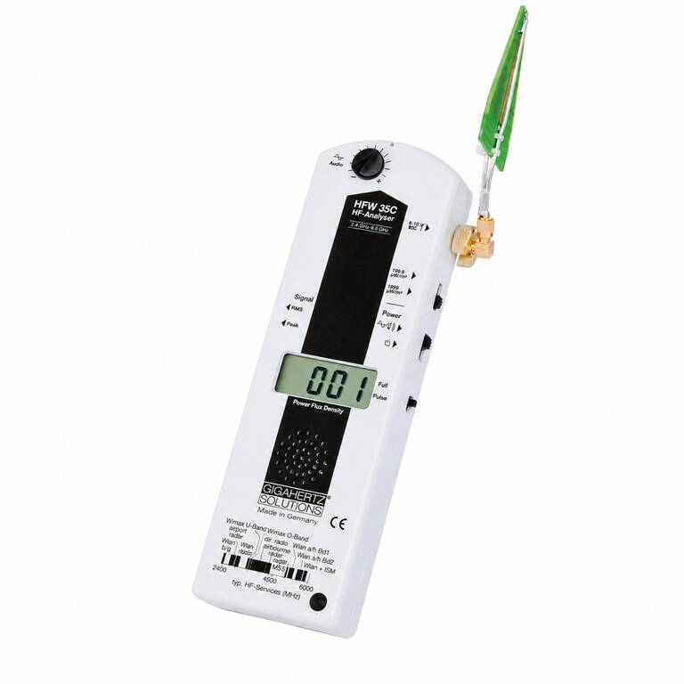
Key features of Gigahertz-Solutions HFW35C Handheld RF Meter
• Frequency range: 2.4-6 GHz
• Power flux density measurement range: 0.1-1999 uW/m2
• Peak and average value display with Full and Pulse measurement options
• Logarithmic-periodic measuring antenna with directional characteristics
• Audio analysis supports identification of pulsed radiation sources
• Quantitative differentiation of pulsed and unpulsed radiation
• 9 V alkaline manganese battery, average operating time: 6-7 hours
• Includes LogPer antenna, antenna cable, battery and detailed manual


Further details of Gigahertz-Solutions HFW35C Handheld RF Meter
The Gigahertz Solutions HFW35C high-frequency RF analyser is designed for measuring frequencies from 2.4-6 GHz. Its frequency range covers the lower and upper WLAN/WiFi bands, Bluetooth, some radar and beam-radio frequencies, as well as the WiMAX bands. It also covers the 5G frequency band between 3.4 and 3.8 GHz. The instrument can be used as a supplementary meter for the HF35C, HFE35C and HF38B analysers and is also suitable for dimensioning WLAN networks.
Gigahertz Solutions HFW35C measurement characteristics
• Frequency range: 2.4-6 GHz
• Power flux density measurement range: 0.1-1999 uW/m2
• Basic accuracy for CW signals including linearity error: +/-6 dB
• Zero point deviation and special digitizing error, rollover: +/-9 digits
• Signal setting: Peak or average value display
• Full/Pulse switch: display of the complete signal or only the pulsed, more specifically amplitude-modulated, fraction
• Quantitative differentiation of pulsed and unpulsed radiation
• The instrument displays the sum of all radiation present at the measurement location
• Frequency-compensated measurement system
The Range setting adjusts measurement sensitivity according to the radiation level. Measured values are displayed directly in the unit used for building biology precautionary values without requiring additional calculations.
HFW35C 2.4-6 GHz LogPer measuring antenna
• Optimized logarithmic-periodic measuring antenna
• Frequency response compensated directly on the antenna
• Antenna with directional characteristics
• Integrated steep-edged high-pass filter
• The filter suppresses mobile radio and DECT frequencies for analysis of the 2.4-6 GHz range
• The special antenna design suppresses interference outside the main receiving direction by approximately 15-20 dB
• The internal high-pass filter provides an additional approximately 40 dB of suppression
The antenna connects to the analyser using an angled SMA connector. The LogPer antenna is inserted into the cross-shaped opening at the front of the instrument. An LED at the antenna tip is provided for checking proper contact of the connection cable. The double semi-rigid antenna cable is designed for several hundred bending cycles without affecting measurement quality.
Gigahertz Solutions HFW35C polarization and directional measurement
With the antenna attached, the meter measures the vertically polarized component when the display is positioned horizontally. Rotating the meter around its longitudinal axis allows other polarization planes to be measured. For horizontal antenna orientation, the entire meter should be rotated rather than twisting the antenna cable.
• The main direction of radiation can be determined by moving the instrument in different directions
• Horizontal polarization can be measured by rotating the instrument by up to 90 degrees around its longitudinal axis
• Changing the measurement position allows local cancellations to be checked
• Reflections inside buildings can cause localized amplification or cancellation
Measurement results may vary with location and time. The manual therefore describes repeating measurements at different times of the day, on working days and weekends, and periodically throughout the year.
HFW35C audio frequency analysis
• Audio signal proportional to modulation frequency and field strength supports identification of pulsed radiation sources
• Audio analysis uses the amplitude-modulated fraction of signals within the 2.4-6 GHz frequency band
• Audio analysis supports identification of pulsed radiation sources such as WLAN/WiFi signals
• Audio analysis includes volume control
Different radio services can operate within the 2.4-6 GHz range. Audio analysis of the amplitude-modulated signal fraction supports identification of their sources.
Gigahertz Solutions HFW35C Peak, Full and Pulse functions
The Signal switch controls signal evaluation. The Peak setting is used to display the peak value of power flux density, while the instrument can also display an average value.
• Peak evaluation
• Average value display
• Full: display of the complete signal
• Pulse: display of the pulsed, more specifically amplitude-modulated, signal fraction
• Quantitative differentiation of pulsed and unpulsed radiation
The measurement range can be extended for strong sources with the separately available DG20_G10 attenuator. The HV20_2400G10 preamplifier provides a factor of 100 preamplification; Pulse measurement mode is required when using it.
HFW35C high-frequency measurement procedure
• Initially set the Range switch to the 1999 uW/m2 measurement range
• If consistently low values are displayed, the finer measurement range can be selected
• Hold the instrument at arm's length with the hand at the rear of the housing
• The audio signal can be used to identify areas with higher exposure levels
• Moving the instrument in different directions can determine the main direction of incoming radiation
• Rotating the instrument around its longitudinal axis allows different polarizations to be examined
• Changing the measurement location allows local spatial variations to be checked
The instrument can be used in measurement procedures for determining total high-frequency exposure and identifying locations where high-frequency radiation enters an area. For measurements in a building, apartment or property, the manual also describes recording individual measurement results.
HFW35C power supply and automatic power-off
• Power supply: 9 V E-block alkaline manganese battery
• Battery included
• Average operating time: 6-7 hours, depending on operating mode
• Low Batt. indicator
• Auto power-off function
• Automatic power-off after approximately 40 minutes of continuous operation
• Automatic power-off approximately 2-3 minutes after Low Batt. indication
• Weight: 0.41 kg
• Warranty: 2 years
After the Low Batt. indication appears, the measurement values are no longer considered reliable and the battery must be replaced. The auto power-off function is provided to conserve battery capacity.
Gigahertz Solutions HFW35C scope of delivery
• HFW35C measuring device
• Plug-on LogPer antenna
• Antenna cable
• 9 V alkaline manganese battery
• Detailed operating instructions with background information
The HFW35C provides a 2.4-6 GHz frequency range, a 0.1-1999 uW/m2 power flux density measurement range, Peak and average value display, Full and Pulse functions, and audio analysis. The plug-on LogPer measuring antenna features directional characteristics, frequency compensation and high-pass filtering.
Gigahertz-Solutions HFW35C Handheld RF Meter related media
 ▶
▶