

- Special Offers
- Transceiver Radio
- Transceiver Accessory
- Antennas
- Antenna Accessory
- Fiber Optics
- Cable
- Connector
- Installation Material
- Installation Tools
- Measuring Equipement
- Body Worn Camera
- Electrosmog
- Telephone
- Baby Monitor
- Fever Thermometer
- Radio Device
- Set-top Boxes
- Personal Protective Equipment
- Motorcycle Helmet Speaker
- Car Equipment
- Voltage Converter
- Dry Cell
- Battery
- Battery Charger
- Emergency Signal
- Amber Signal
- Sound Signal
- Light and Sound Signal Accessory
- Traffic Engineering
- LED Lamp
- Smart Home
- Mosquito Repellent Device
- Market - Other Products
- Discontinued Products
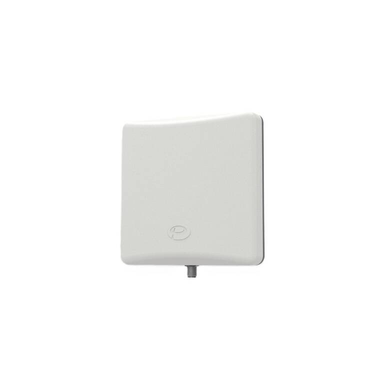
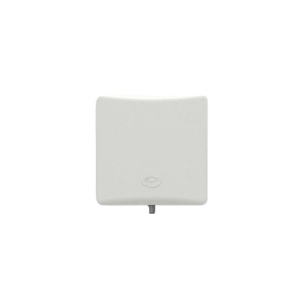
Panorama Antennas W24-58-CP-9 Dual Band WiFi Panel Antenna
Key features of Panorama Antennas W24-58-CP-9 Dual Band WiFi Panel Antenna
• Directional WiFi panel antenna for indoor and outdoor installation
• Frequency range: 2400-2485 MHz and 4900-6000 MHz
• Peak antenna gain: 9 dBi, impedance: 50 Ohm
• Azimuth 3 dB beamwidth: 60 degrees (2.4 GHz), 90 degrees (5 GHz)
• Vertical polarization, SMA socket connector
• Dimensions: 93 x 93 x 25 mm
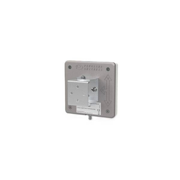
• Wall or mast mounting with supplied 90-degree adjustable bracket
• Operating temperature: -30 to +70 C


Further details of Panorama Antennas W24-58-CP-9 Dual Band WiFi Panel Antenna
The Panorama Antennas W24-58-CP-9 is a dual band directional WiFi panel antenna designed for 2.4 GHz and 5 GHz WLAN applications. It is suitable for indoor and outdoor installation, including point-to-point links, wide area WiFi coverage, and applications in buses, trams and trains. The antenna features 9 dBi peak gain, an SMA socket connector and an adjustable mounting bracket.
Panorama W24-58-CP-9 WiFi Panel Antenna Applications
• Indoor and outdoor WiFi coverage
• 2.4 GHz and 5 GHz WLAN applications
• Point-to-point links
• Wide area coverage using a wide radiation beam
• WiFi coverage in buses, trams and trains with minimum coaxial cable runs
• Installation of two antennas side by side to provide a 2x2 MIMO antenna system
• Multiple antennas for sectored operation
The antenna features a directional radiation pattern. Its wide beamwidth in both azimuth and elevation planes makes it suitable for wide area coverage. Multiple antennas can be installed together for MIMO or sectored operation.
W24-58-CP-9 Electrical and RF Specifications
• Frequency range: 2400-2485 MHz and 4900-6000 MHz
• Operational band: 2.4 GHz and 5 GHz WLAN
• Peak isotropic gain: 9 dBi
• Radiation pattern: Directional
• Azimuth 3 dB beamwidth at 2.4 GHz: 60 degrees
• Azimuth 3 dB beamwidth at 5 GHz: 90 degrees
• Polarization: Vertical
• Impedance: 50 Ohm
• VSWR: Maximum 2:1
• Maximum input power: 50 W
• RF connector: SMA socket
Typical H-plane radiation patterns and three-dimensional radiation plots are available for 2400 MHz and 5400 MHz. The typical VSWR curve represents measurements taken in free space without additional cable.
Panorama W24-58-CP-9 Mechanical Specifications
• Height: 93 mm
• Width: 93 mm
• Depth: 25 mm
• Material: LEXAN EXL9330 and die-cast aluminium
• Colour: Signal White
• Operating temperature: -30 to +70 degrees Celsius
• Mounting: Wall or mast
• Wind load: 11 N at 150 km/h
• Radome: UV-stabilized
• Radome flammability classification: UL f1/V-0/5VA
The antenna features a compact square housing and an adjustable mounting arrangement. Its mechanical design supports both wall and mast installation.
W24-58-CP-9 Antenna Installation and Adjustment
• The supplied mounting bracket provides 90 degrees of orientation adjustment, with 45 degrees in either direction from the centre position
• The bracket features four 4.2 mm diameter mounting holes suitable for 4 mm or No. 8 screws
• Mounting hole centres: 22 x 22 mm
• The bracket can be disassembled and used as a drilling template
• Supplied screws and washers are used to attach the bracket to the antenna
• Wall mounting requires two appropriate screws, which are not supplied
• Mast mounting can be performed using a jubilee clip, which is not supplied
• Orientation arrows on the rear of the antenna indicate the mounting direction
• The installation instructions illustrate mounting orientations for horizontal and vertical polarization
• For external installation with vertical polarization, the connector must face downwards
• Where possible, maintain at least 300 mm clearance from surrounding obstructions
All mounting hardware must be fully tightened, and the antenna direction must be checked during installation. Wall mounting screws should be selected according to the mounting surface. Before drilling, ensure that drilling into the selected surface is safe.
MIMO Installation Considerations
• Two W24-58-CP-9 antennas can be installed side by side to provide a 2x2 MIMO antenna system
• Multiple antennas can be installed at the same location
• The optimal relative positioning uses vertical separation
• Minimum vertical separation between antennas: 150 mm
Connector, Cabling and Commissioning
• Antenna connector: SMA socket
• Route the coaxial extension cable to the connected equipment
• Cable routing must not create a hazard
• A drip loop should be considered before cable entry into a building or enclosure
• Weatherproof electrical tape can be used to waterproof the SMA connector joint
• Self-amalgamating tape is recommended, with significant overlap between turns
• Tape overlap should run opposite to the predicted direction of water flow
• Carry out a VSWR check during commissioning
• Required commissioning VSWR measurement: Less than 2.0:1
Safety and Environmental Information
• The antenna is an electrical conductor and must not be installed where the antenna or installer could contact overhead power lines
• An inline surge arrestor should be considered in locations vulnerable to lightning
• The antenna must be installed so that no person is within 30 cm during operation
• RoHS 2 compliance: Directive 2011/65/EU and subsequent amendments
• Waste electrical and electronic equipment must be collected separately for recycling
• Installation should be performed by a properly qualified installer in accordance with local laws and regulations